SCF Calculation of tubular joint SCF
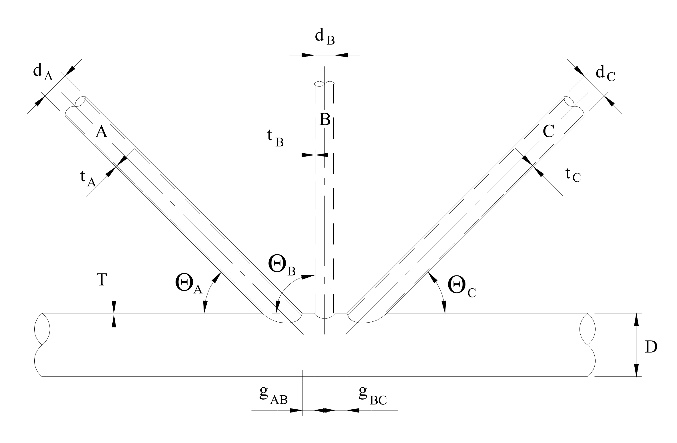
Many offshore structures are fabricated with tubular members. The connections between the different tubular members are denoted tubular joints. A tubular joint is made up of a chord (element of largest diameter) and one or more braces.
The classification of a joint is not solely determined by the geometry, but also by the axial loads in the members. For example, if the axial force in one brace in an X-joint is much less than the other, the joint would be classified as a T-joint.
Although real structures are composed of multiplanar joints, the treatment of simple planar joints can be used if the members are within $\pm 15^\circ$. The nominal axial and bending stresses are multiplied by the appropriate Stress Concentration Factor (SCF) to obtain the stress at the crown and saddle of the chord and brace1. The resulting stresses can be combined to find the resulting stresses along the perimeter of the chord-brace intersection as described in DNV RP-C203 2. Once the Hot Spot Stresses (HSS) are calculated, a fatigue calculation can be performed.
The equations used for the determination of the tubular joint SCF 3 4 are based on the equations developed by Efthymiou 5. A comprehensive comparison of tubular joint SCF parameteric equations can be found in "Stress Concentration Factors for Simple Tubular Joints, Assessment of Existing and Development of New Parametric Formulae"6.
CRM Engineering has developed an online calculator of the equations.
SCF Calculation of tubular joint SCF via FEA
If the joint parameters are outside the formula validity or if no SCF correlation exists for a joint geometry, a finite element analysis can be performed to calculate the SCF. Examples of such a joint would be a chord comprised of a jacket and pile with a grouted annulus or a non-tubular section. A methodology for calculating the SCF from a finite element analysis is given in DNV RP-C203 1.
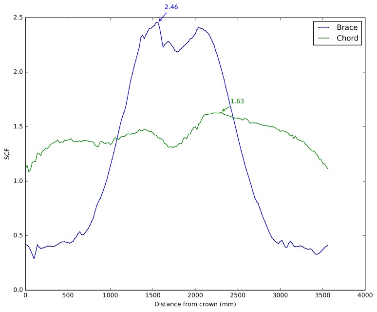
The SCF calculation around the circumference of the brace-chord intersection is tedious and time consuming. CRM Engineering has developed an automated method that reduces the time and cost of extracting the SCF. At each node along the intersection between the brace and the chord, a path is created on the brace and the chord normal to the intersection. For each node on the intersection, a local coordinate system is created such that the local x-axis is normal to the intersection and the local z-axis is normal to the brace or the chord. The local $\sigma_{xx}$ and $\tau_{xy}$ is extracted along the paths and the SCF calculated, using the larger of Method A and Method B.